Solving Engineering’s Toughest Geometry Challenges with CADfix: A Comprehensive Look at the 8 Core Technologies
Mark Gammon, Technical Director/Product Manager, ITI
Henry Bucklow, Software Developer, ITI
Steve Utterdyke, Senior Technical Consultant, ITI
In today’s digital engineering world, model integrity is everything. From design to simulation, from plant layout planning to additive manufacturing, the quality and compatibility of CAD geometry can make or break a project. Yet, across industries, companies continue to struggle with inefficient data exchange, bloated 3D models, visualization challenges, additive manufacturing issues, and the inability to scale through automation.
These aren’t just isolated problems. They are systemic bottlenecks that block innovation, delay programs, and add risk to the product development process.
CADfix is purpose-built to eliminate these geometry roadblocks. Rather than positioning CADfix as one monolithic tool, it is better understood through the 8 core services it delivers across the engineering and manufacturing lifecycle. Each service tackles a specific geometry challenge with precision while integrating seamlessly into enterprise workflows through CADfix DX, PPS, Viz, Meshing, and API.

1. Exchange – Reliable CAD Data Interoperability
Delivered by: CADfix DX and CADfix API
The Challenge: 3D product definition data comes in a huge range of formats and levels of complexity these days. Gone are the days when an IGES or STEP file was enough to transfer the basic 3D geometry of a design. The growing adoption of model-based design (MBD) workflows means more key product data is now carried by the CAD file. The content has been extended way beyond the 3D geometry to include valuable meta data such as material and physical properties, product structure, organizational classifications, user defined tags, etc. Robust exchange of complex meta data requires an exchange tool with extensive access to all forms of data held in a CAD file, not just the 3D geometry element.
The basic 3D geometry has also become more complex with the introduction of facet-based geometry as an alternative to the traditional precise 3D CAD geometry. The growth of facet-based geometry and hybrid geometry (CAD + facets) has been driven particularly by the expanding adoption of the digital twin paradigm. Bi-directional conversion between precise CAD and facet geometry can be a significant barrier to efficient exchange of design data, e.g. interfacing to a system that accepts/generates only one of the geometry formats.
Today, effectively exchanging complex CAD model data, in all its forms, is a major time-sink and cost to organizations, often requiring manual intervention. Robust, reliable, automatic CAD data exchange is critical to compressing design cycle times and fundamental to leveraging the potential of AI-optimized design processes.
The CADfix Solution:
- CADfix provides best-in-class CAD interoperability with extensive bi-directional support for native CAD formats (CATIA, NX, Creo, SolidWorks, SolidEdge, AutoCAD, Inventor, MicroStation, Revit, NavisWorks,…), neutral CAD file formats (STEP, JT, PLMXML, DXF, IFC,…) and facet-based formats (STL, OBJ, glTF, FBX, USD,…)
- CADfix’s use of official APIs to read/write native CAD data gives deep access to valuable non-geometric data, such as assembly trees, properties, meta data, user-defined attributes, etc. This enables more complete exchange between systems.
- Conversion between CAD geometry and facet geometry or extraction of facet-only geometry from hybrid models, supports adoption of digital twin workflows.
- Robust automation is provided through a command line batch interface or enterprise level web-based/watched folder managed exchanges.
Use Case 1: An automotive OEM uses CADfix to exchange CATIA V5 models with the automotive integrator via the PLMXML format. CADfix augments the PLMXML data automatically with the required mass properties and user-defined attributes required by the integrator.
Use Case 2: A consumer electronics company uses CADfix to exchange large complex Creo assemblies with their end user documentation system. CADfix’s use of the official Creo and JTOpen APIs enables extraction and exchange of key non-geometric meta data.

2. Clean-up – Advanced Repair, Healing, and Simplification
Delivered by: CADfix DX
The Challenge: CAD models are, in many scenarios, created solely with the goal of being the master definition of a product for the purpose of manufacturing. They often contain high levels of realism, such as filleted/rounded edges, company logos, screw threads, etc. This high level of detail can lead to difficulties in re-using the CAD geometry for other downstream purposes, for example CAE simulation where small details can be costly in mesh generation, or in sharing with supply chain partners where the IP held in the fully detailed model is proprietary and sensitive. At a lower geometric level, complexity can result in errors or faults in the geometry that were not visible in the original CAD system but become apparent when exchanged with another downstream tool.
The definition of valid geometry differs from system to system due to proprietary differences in fundamental geometric algorithms and properties. Issues such very short lines, sliver faces, closed surfaces, invalid connectivity and mathematical accuracy are common, requiring costly manual re-work. Another source of costly manual work can arise where the downstream tool requires some derived geometry not available in the master CAD, for example the geometry of the air-flow passages in a multi-component ventilation assembly where the geometry required is the “air” around/within the “metal”. Complex transformations of CAD geometry into a new derived geometry are central to many simulation-driven design cycles and are becoming more so with the advent of AI-driven optimization.
Cleaning up a master CAD geometry for re-use in a wide variety of downstream applications requires a very powerful and flexible geometry manipulation tool with unique advanced operations typically not found as part of a mainstream CAD system.
The CADfix Solution:
- CADfix offers a wide range of advanced clean-up operations: hole removal, fillet removal, shrink-wrap, imprinting, face and body joining, feature removal, deconstruction, plus many more.
- An extensive toolset of model validity checks with automatic fixes that address the low-level exchange failures between different systems.
- Robust body joining, shrink-wrapping and internal detail removal for IP protection
- Powerful splitting tools that speed up the breaking down of complex parts into simpler parts suited for downstream re-use
- Supports automated clean-up workflows through a command line batch interface with operations and parameters controlled through a user-defined configuration file.
- Advanced automation through a powerful scripting interface
Use Case 1: A defense contractor removes thousands of small holes and fillets automatically from assemblies using CADfix clean-up, cutting simulation setup time by 60%.
Use Case 2: An automotive OEM uses CADfix clean-up to shrink-wrap complex engine block components for IP protection before releasing to their supply chain.

3. Simplify – Lightweight Models for Plant & Process
Delivered by: CADfix PPS
The Challenge: Large scale engineering and architectural design processes, such as industrial plant layouts, ship interiors, food processing assemblies often contain detailed pieces of equipment that carry an excessive level of detail, way beyond what is required by plant design engineers. Highly detailed, heavyweight items such as engines, pumps, motors, fans, radiators are added into the plant design software because they are required for validation of the design, however it’s common to find the only geometry format available for these pieces of equipment is the fully featured CAD manufacturing model from the OEM supplier.
These large CAD models typically contain excessive CAD realism, such as holes, fillets, nuts/bolts/washers, company logos., etc. These unnecessary levels of detail can seriously cripple plant design tools by slowing load and display times and massively bloating database sizes. Plant designers typically need a much simpler outline of the detailed equipment, retaining the key bulk properties and key connector locations. Achieving this complex simplification using manual tools is a major time sink leading to higher project costs and increased schedules.
The CADfix Solution:
Industry-leading automatic geometry simplification tailored to the needs of plant designers and the 3D geometry tools they use.
- Smart deconstruction of complex CAD geometry is combined with multiple primitive identification and geometric fitting algorithms to auto-generate lightweight replacements for complex CAD parts.
- Automatic detection of pipe centerline networks enables the isolation and preservation of key connector features, such as flanges and nozzles, while enabling robust filtering out of many non-essential.
- Model size reduction through intelligent identification of irrelevant details such as fasteners, logos, floor grills and non-visible internal parts.
- Model complexity is typically reduced by orders of magnitude while retaining key design/integration features.
- Automatically removes internal components and redundant geometry.
- Provides user control over the simplification level with access to tune key parameters.
Use Case 1: A utility company reduces a complex power plant model by 85% using CADfix PPS, cutting digital twin load times from 12 minutes to under 1 minute.
Use Case 2: A plant design software vendor embeds CADfix simplification technology into their plant design software giving their users a faster design experience saving days/weeks in design cycles.

4. Visualize – Seamless Integration with Digital Twins and XR
Delivered by: CADfix Viz
The Challenge: Large complex CAD models are often too heavy or incompatible for AR/VR platforms, web-based product configurators, and digital twin environments. Generating optimal visualization meshes at various levels of details (LOD) using manual design tools costs a lot in wasted hours and delays. Automatically deciding how and where to reduce the level of detail in a complex CAD model is not trivial and requires intelligent identification and analysis of the relative visual cost of various geometric features. Removal and closure of small holes and gaps can enable large reductions in mesh sizes, particularly coupled with filtering out of non-visible internal features.
Decimation is a key technology for generating a range of visualization meshes at different levels of detail and file size, however if it is crudely deployed it can introduce negative visual artefacts. Intelligent damage-sensitive decimation enables low count meshes to be produced with minimal loss of visual quality. Shrink-wrapping is another powerful technology essential for achieving low count polygon meshes, particularly effective on assembly models with sizeable air gaps that need to be closed.
Finally, the export of multiple LOD meshes along with the valuable product structure, meta data and attributes to one of the modern formats require careful mapping and construction of the correct scene graph.
The CADfix Solution:
- CADfix Viz converts CAD geometry into a range of lightweight formats (glTF, FBX, JT, USD, etc.) with automatic mesh sizing controls and level-of-detail (LOD) control.
- Unique CAD model feature identification (holes, protrusions, lettering, etc.) enables automatic detail suppression while preserving surrounding detail
- Filtering out of proprietary internal geometric details is supported for IP protection.
- Industry leading decimation capable of optimizing mesh sizes while meeting target quality constraints on file size and mesh smoothness.
- Three levels of shrink-wrap mesh generation offers detail preservation for high quality meshes all the way to gross simplification for very low detail meshes.
- Mid-surface idealization of thin-walled objects
- Enables smooth integration into AR/VR, Unity, Unreal, and web platforms.
Use Case 1: A consumer electronics company uses CADfix Viz to generate glTF files from SOLIDWORKS assemblies for a web configurator, cutting load times and improving the end user experience.
Use Case 2: A US defense company uses CADfix Viz to automate the generation of FBX files from Creo assemblies for use in generating marketing videos. The smart level-of-detail algorithm in CADfix VIZ results in optimal detail capture but with small file sizes.

5. STL – High-Quality Faceted Geometry Output
Delivered by: CADfix DX
The Challenge: The STL geometry format provides a simple, widely supported means to describe a 3D surface geometry as a mesh of triangles. Due to its straightforward format and decades-long history, it has been adopted in many industrial applications, with heavy use in additive manufacturing, and as a common geometry definition for simulation tools. In many situations, a basic STL representation of a CAD part can be easily generated from a CAD system. However, for applications where the accuracy and quality of the STL facets is critical, the basic STL exports from most CAD systems can fall short, costing lost time due to lack of precision, poor capture of features, or unsuitable triangle shapes causing numerical error in downstream processes.
An STL file is an approximation of a master CAD geometry, so its generation involves a trade-off between accuracy when capturing curved shapes versus the number of facets generated. Too many facets and downstream processes often struggle; too few and representation errors mean the file is not fit for purpose. Robustly generating high-quality STL models requires a tool with automatic yet configurable sizing controls (controlling curvature capture and facet quality) that can be easily configured and integrated into automated workflows.
The CADfix Solution:
- CADfix STL delivers rapid, robust and reliable generation of watertight STL files with guaranteed accuracy of detail capture
- Intelligent sizing rules based on analysis of the CAD geometry produce high quality results with minimal user intervention
- Full control over accuracy is provided to ensure precision requirements are met
- CADfix STL offers two tessellation algorithms: one aimed at generating a minimal number of triangles with no constraints on facet shape, and the other for generating larger numbers of approximately equilateral facets
- Automation is central to CADfix STL: a powerful, highly configurable mesh recipe mechanism enables complete control over sizing parameters, and allows easy reuse of these parameters over multiple models or for batch processing
- Attributes from the CAD model can be used to automatically drive localization of mesh styles and refinement of mesh sizing, using metadata such as layers and labels
Use Case 1: CFD engineers use CADfix STL to generate highly controlled STL meshes optimized to meet the needs of OpenFOAM and snappyHexMesh while satisfying strict geometric accuracy criteria. They use local sizing rules, driven by CAD attributes, to relax the mesh size and shape constraints in less critical areas, optimizing overall pipeline speed.
Use Case 2: A Japanese electric motor manufacturer uses the unique non-manifold geometry capability of CADfix to generate run-ready STL models that automatically capture and identify the shared contact regions between components, enabling simulation to be integrated into a design optimization workflow.
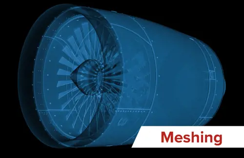
6. Mesh – High Quality Automatic CAE Mesh Generation
Delivered by: CADfix Meshing and CADfix DX
The Challenge: Mesh generation remains a bottleneck in simulation processes. Raw CAD is rarely mesh-ready:. sliver faces, gaps, and excess detail cause meshing failures, slow simulation convergence, and wasted computational resources due to excessive element count. A robust, reliable, and automated meshing process is essential for automating CAE simulation, enabling optimization loops, dataset generation for AI training, and democratization of CAE simulation to non-expert users. Hexahedral meshing comes with further challenges, as models must be partitioned into 6-sided blocks before they can be meshed, a time-consuming process requiring significant expertise.
The CADfix Solution:
- Repairs and defeatures geometry specifically for CAE with powerful automation
- Smart sizing defaults driven by analysis of the CAD model, with full manual control
- Mesh Recipes allow complete localized control over all meshing parameters – size, style, element type – automatically controlled by CAD metadata such as layer or label
- Linear and quadratic elements, with tetrahedral, hexahedral, and mixed element types
- Parallel tet meshing of multi-part models to reduce runtime
- Export to CAE solvers like Nastran, ANSYS, and Abaqus
- Unique and powerful automated tools for hexahedral splitting allow rapid generation of hex meshes, significantly reducing user workload
- Structured meshing sizing constraints are automatically resolved, simplifying mesh sizing for hex meshing
- Integrates meshing into broader workflows with support for all major CAD systems
Use Case 1: Automated highly robust quadratic mesh generation for structural analysis
Use Case 2: A turbine manufacturer uses CADfix Meshing to prepare complex turbomachinery geometry for stress and thermal analysis. By preparing mixed hex/tet meshes, they reduce solver time by 25%.

7. Morph – Geometry Optimization for Simulation and AI
Delivered by: CADfix DX and CADfix API
The Challenge: Parametric CAD system design geometry is very difficult to update to reflect large-scale changes, especially if these changes were not foreseen by the original designer. For example, deriving an early prototype of a new car variant by reshaping a fully detailed previous design, or applying bulk warpage compensation adjustments across an entire complex part. The design changes needed in these examples cannot be expressed as modifications to the CAD system feature parameters because the changes are global, fundamental, shape changes; attempting to apply such changes parametrically would quickly lead to update failure.
The democratization of CAE simulation, combined with new advances in AI-based physics models and optimization algorithms, is making global shape optimization commonplace. To unlock these new ground-breaking designs while still retaining the hard-earned IP and expertise embodied in existing CAD designs requires an advanced global geometry morphing capability: a capability able to accept radical new shape inputs, update an existing design, and export a new re-usable CAD part, ready for further downstream use.
The CADfix Solution:
- CADfix Morph is a unique technology that enables mainstream CAD geometry to be robustly and accurately morphed.
- Deformations provided by CAE simulations, 3D scans and AI driven shape changes are supported.
- The Morph technology smoothly deforms existing CAD curve and surface geometry to retain key original design intent while adapting to a new optimal shape.
- CADfix Cleanup and Exchange technologies ensure the morphed result can be reliably exported and re-used by a wide range of standard downstream tools
- Morph supports applications like casting, topology optimization, and generative design.
Use Case 1: In collaboration with Hexagon/Simufact, CADfix Morph is used to automatically update a CAD design geometry to compensate for shape changes predicted by a manufacturing simulation run.
Use Case 2: CADfix Morph, coupled with an ANSYS™ thermo-mechanical simulation, is enabling a titanium casting manufacturer to rapidly derive the initial near-net-shape geometry for a novel titanium casting process.

8. Diff – CAD to Scan Comparison
Delivered by: CADfix DX
The Challenge: 3D scans and point clouds are becoming a critical form of geometry in diverse industrial use cases, across reverse engineering, validation of manufacturing quality, human medical scans, and surveys of large-scale architectural/plant installations. The applications of scan geometry are varied, but a common need is to compare the scan data to some reference “truth” design, such as a master CAD part or a complete plant layout, and to identify, quantify, and potentially reuse the differences. Extracting and reusing scan-to-CAD differences is particularly important for enabling simulation of in-service components, such as evaluating the effect of real-world wear on jet engine compressor blades.
Another growing application of scan-to-CAD comparison is in compensating a design geometry to allow for manufacturing shrinkage or warpage, such as in additive manufacturing, injection molding, or specialized casting processes. Finally, 3D scans by their nature are typically very large and cumbersome to work with, often resulting in severe performance penalties that can make their effective re-use nonviable. Robust data reduction strategies are necessary to ensure efficient downstream processing, without sacrificing accuracy.
The CADfix Solution:
- Scans and point clouds can be imported from common formats.
- Data reduction tools allow massive scans to be reduced to smaller, yet still representative, subsets for faster processing.
- Multiple registration/alignment algorithms are available, including a novel medial axis-based non-rigid registration unique to CADfix.
- Bi-directional comparisons between scan and CAD report differences in detail with visualization of hot spots.
- Extraction of differences for validation, inspection, quality assurance and downstream re-use.
- Connection to the CADfix Morph technology for automatic design modification driven by scan geometry, e.g. for manufacturing warping/shrinking compensation
Use Case 1: An automotive supplier uses CADfix Diff to compare scanned parts against CAD for inspection reports.
Use Case 2: A medical appliance manufacturer uses CAT and MRI scans to extract morphing differences relative to a CAD template, to tailor a prosthetic design to match each patient.
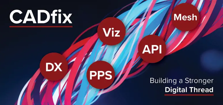
Building a Stronger Digital Thread with CADfix
Each of the eight CADfix services maps directly to the specialized CADfix products: DX, PPS, Viz, Meshing, and API.
Together, they eliminate geometry barriers across design, simulation, manufacturing, and visualization workflows.
Whether you’re exchanging CAD data with suppliers, preparing a model for CAE, simplifying a massive plant layout, exporting STL for additive manufacturing, or building a digital twin, CADfix ensures models are accurate, lightweight, interoperable, and downstream-ready.
In a world where digital transformation hinges on seamless data flow, CADfix is the glue that holds the digital thread together.
Want to see CADfix in action?
Connect with our experts to schedule a demo and discover how CADfix can accelerate your workflows and simplify your most complex geometry challenges.