CAD to CAE Solutions - CADfix Bridges the Gap Between CAD and Simulation
Unlock the full potential of your CAD data for CAE with ITI's CADfix solution. The innovative CADfix tools are designed to automatically and interactively repair and transform CAD geometries, ensuring optimal performance in downstream simulation applications.
Accelerating the CAD to CAE Process - Overcoming Common Challenges
In the CAE world, analysts frequently grapple with CAD model issues that lead to meshing failures, excessive model rework, and prolonged analysis lead times. CADfix addresses challenges such as:
- Overly complex, badly defined, and corrupt geometry
- CAD model features impacting mesh ability
- Removal of fillets, small holes, small faces, short edges, and other CAD model artifacts that cause meshing constraints
- Customizable for different CAD sources and CAE packages, our solutions include functions like collapsing short edges, removing holes, joining edges and faces, fillet removal, feature detection, and more.
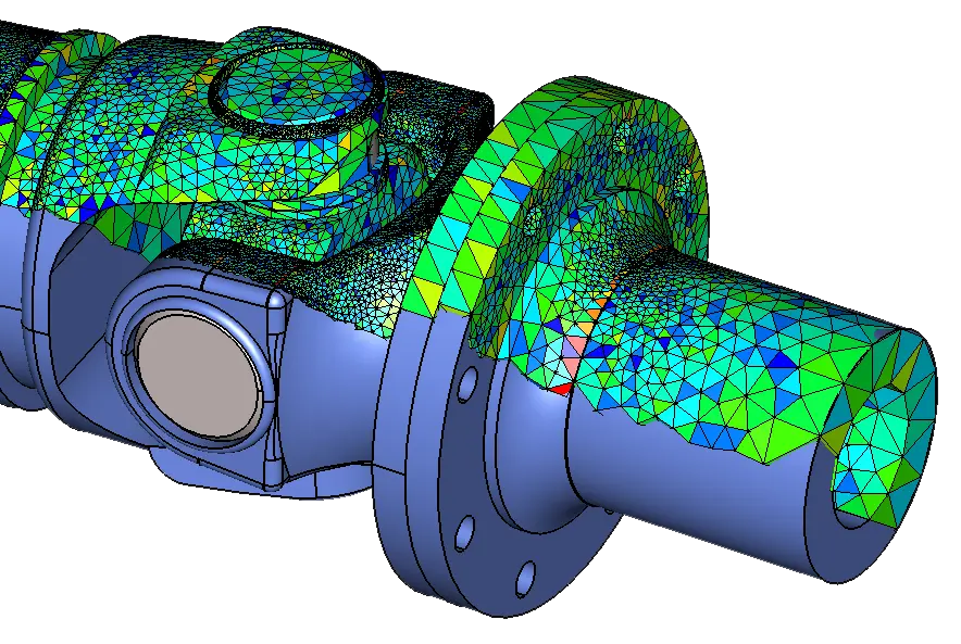
Master Model-Driven FEA, CFD, EM Solutions - Streamlining Analysis
With product design cycles becoming shorter, simulation tools that provide timely results are crucial. CADfix helps ensure that FEA (Finite Element Analysis), CFD (Computational Fluid Dynamics), and EM (Electromagnetic) analysis are seamlessly driven off the master model CAD data. However, preparing CAD data for analysis can be time-consuming due to interoperability challenges.
ITI's CADfix, positioned uniquely in the CAD-to-CAE data flow, resolves these challenges. It reads and writes multiple geometric formats, repairs poor-quality geometry, and simplifies complex definitions, providing CAE analysts with robust geometric definitions for their analytical needs.
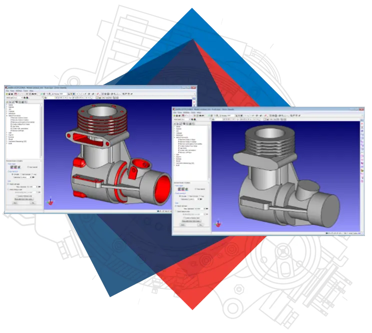
CADfix - Your Solution for Data Exchange and Reuse
CADfix, born out of decades of research and development, solves data exchange and re-use problems between diverse engineering systems and applications. It allows users to import CAD data, repair and manipulate it to suit downstream applications, eliminating the need for expensive CAD model repair and rework. True interoperability is achieved through a range of automatic and manual geometry manipulation tools.
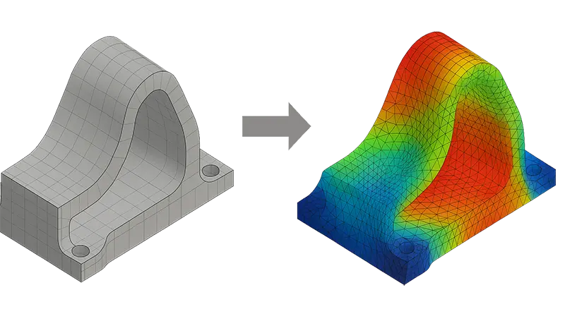
Geometry Morphing
Most CAE analysis can generate a displaced mesh that represents the deformed shape of a component under operating conditions. Multi-disciplinary analysis and automatic shape optimization are two important scenarios where the deformed mesh from one analysis needs to be used as the basis for a second dependent CAE analysis. Converting deformed mesh to accurate deformed CAD geometry may also be required for further design or analysis work and ultimately manufacturing.
CADfix can accurately morph or deform an original CAD model geometry to match displacement results from CAE. The CADfix morphing process generates smooth, well-defined and accurate model geometry that can be exported back to CAD as a usable model, or to CAE for re-meshing and further analysis.
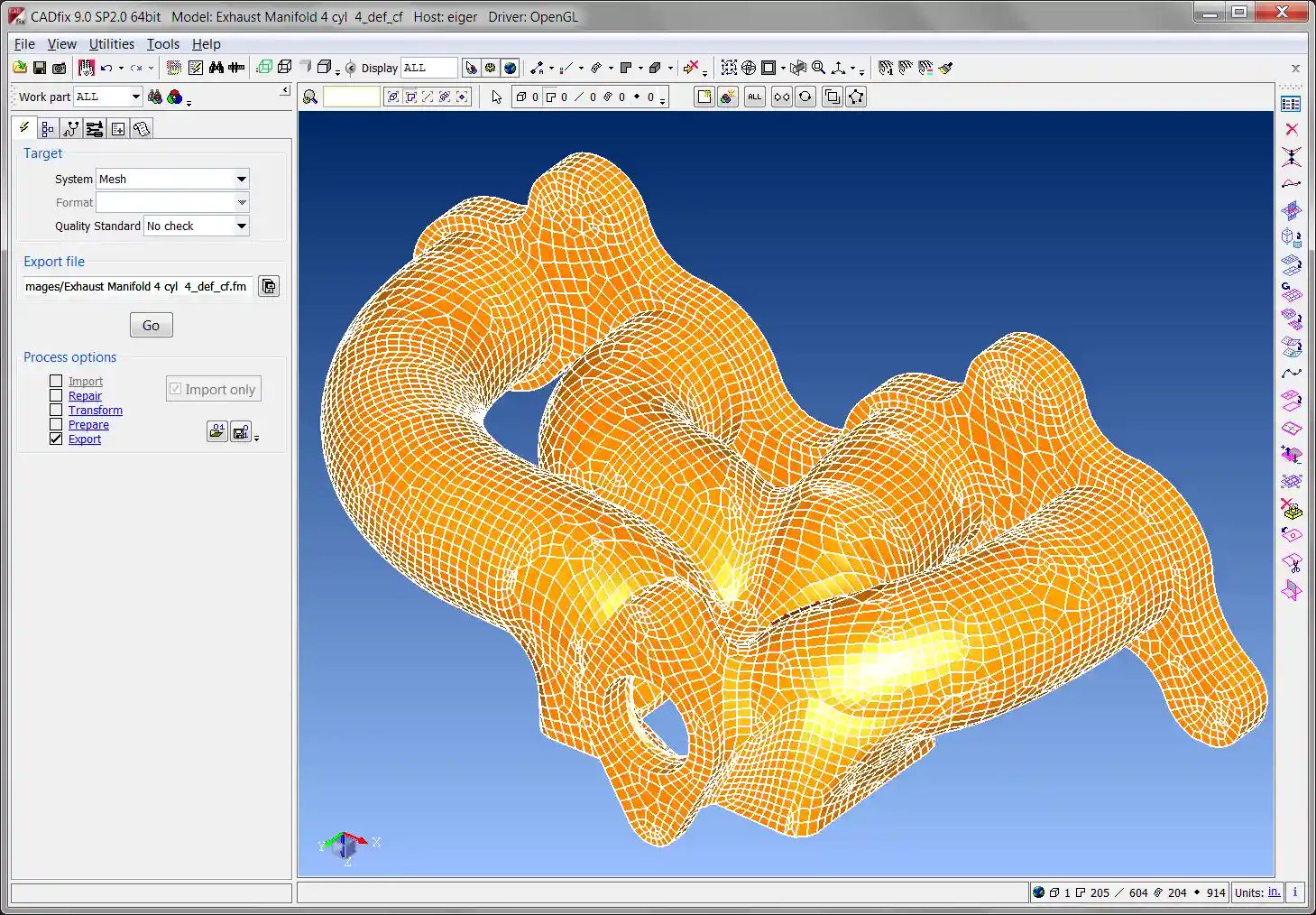
CADfix Geometric Reasoning Technology
The CADfix Geometric Reasoning technology is poised to revolutionize advanced geometry processing applications. Leveraging the CADfix Medial Object (or Medial Axis Transform), it provides advanced geometry transformation and partitioning solutions applications such as mid-surface computation, CFD domain partitioning, machine tool cutter path definition, feature recognition, and more.
Discover the future of CAD to CAE transformation with ITI's cutting-edge solutions. Contact us to explore how our technology can elevate your simulation workflows.
Contact Us Today
Choose ITI for CAD translation and conversion solutions that redefine interoperability and empower your design processes.